

What is eSPI?
The Enhanced Serial Peripheral Interface (eSPI) is an Intel-defined communication protocol designed for modern computer motherboards and embedded systems. It acts as a bridge connecting the Platform Controller Hub (PCH)—the system’s main chipset—with various peripheral components such as the Embedded Controller (EC), BIOS flash memory, TPM, and other low-speed devices.
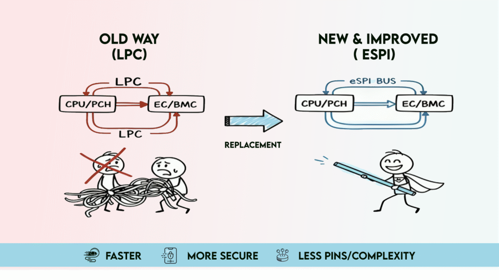
Why eSPI Was Introduced?
eSPI was introduced to replace older communication standards like the Low Pin Count (LPC) bus and, in some cases, the traditional SPI interface. By doing so, it provides a faster, more power-efficient, and scalable method of transferring control and data between the chipset and peripheral devices, making it the preferred interface in modern Intel-based platforms.
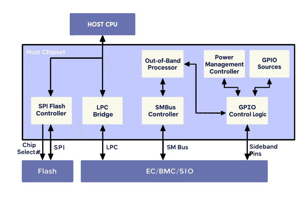
The Low Pin Count (LPC) bus is a computer interface introduced by Intel in 1998. It was designed to connect low-bandwidth, legacy devices—such as BIOS ROMs, Super I/O chips, and TPM modules—to the CPU in IBM-compatible personal computers
The LPC bus served as a dependable interface for many years, but it struggled to keep up with modern system demands. Operating at just 33 MHz with 133 Mbps bandwidth, it required 13 pins and 3.3V signaling, making it inefficient for today’s compact, low-power designs. Additionally, its reliance on sideband signals added to the complexity and pin usage.
To address these challenges, Intel introduced the Enhanced Serial Peripheral Interface (eSPI). The eSPI specification was built to:
- Reduce pin count by using in-band signaling
- Enable low-voltage I/O for better power efficiency
- Replace sideband signals with virtual channels
- Deliver scalable bandwidth and real-time flash sharing
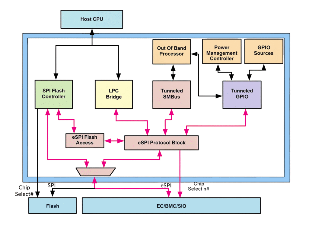
eSPI System Topology?
An eSPI system consists of one controller (typically a chipset) and one or more targets such as an EC (Embedded Controller), BMC (Baseboard Management Controller), or SIO (Super I/O).
The controller governs communication, ensuring that only one Chip Select# is active at a time.
Common configurations include:
- Single Controller–Single Target
- Single Controller–Multiple Targets
- Multiple Channels per Target
Each target communicates over independent channels that share the same physical bus — improving modularity and scalability.
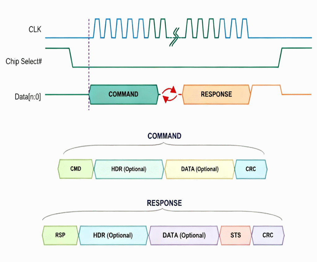
Key Transaction Phases
- Command Phase – Controller initiates communication with command opcode and optional header/data.
- Turn-Around (TAR) – Bus turnaround for the target to take control of data lines.
- Response Phase – Target responds with data or status.
- Alert Phase – Target signals asynchronous events via ALERT# or I/O pins.
![]()
![]()
eSPI Protocol Architecture
The eSPI protocol stack is divided into three layers:
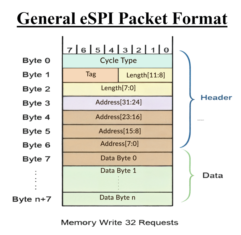
a. Transaction Layer
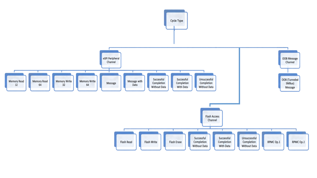
Defines packet format, cycle types, and data flow between controller and targets.
Supports both posted and non-posted transactions, split completions, and WAIT_STATE insertions for synchronization.
The summary of cycle types supported over the eSPI interface is shown in the flow chart below.
b. Link Layer
Handles data encoding, error detection, and cyclic redundancy check (CRC-8).
Ensures reliable data transfer with support for Single, Dual, and Quad I/O modes
c. Physical Layer
Defines the physical signaling, clocking, and electrical behavior for eSPI pins — designed for low-voltage and low-power operation.
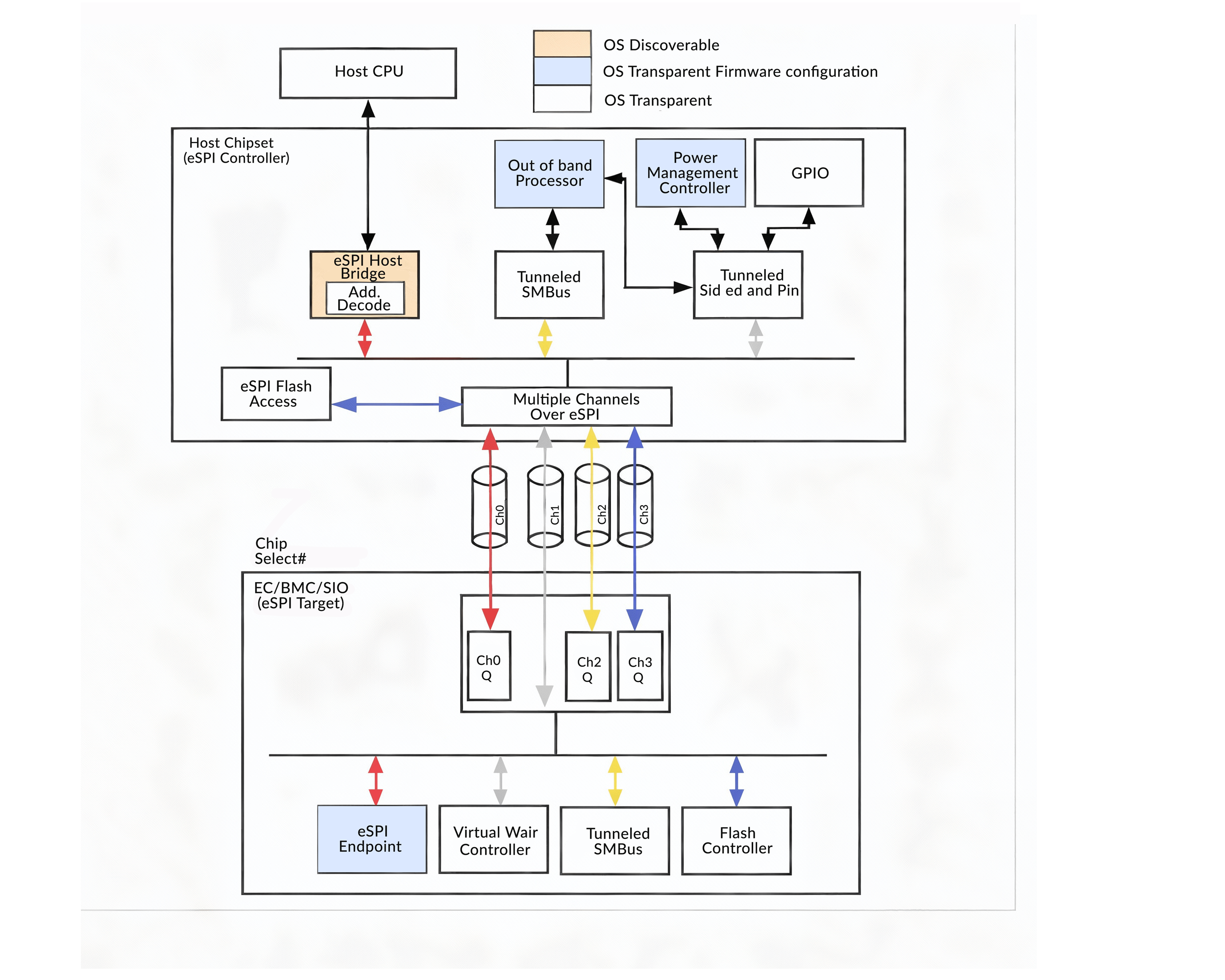
eSPI Channels
The protocol supports multiple logical channels that operate independently over a shared bus:
- Each set of the put_*/get_*/*_avail/*_free associates with the command and response of a corresponding channel.
- There is no ordering requirement between traffics from different channels.
- The number and types of channels supported by a particular eSPI target is discovered through the GET_CONFIGURATION command issued by the eSPI controller to the eSPI target during initialization,The eSPI target can only advertise which of the channels are supported.
- The assignment of the channel type to the channel number is fixed.
- eSPI Peripheral transactions always use Channel 0 & PUT_PC/ PUT_NP/ GET_PC/ GET_NP/ PC_FREE/ NP_FREE/ PC_AVAIL/ NP_AVAIL commands and status fields are used for Channel 0 access.
- Virtual Wires are communicated through Channel 1 & PUT_VWIRE/ GET_VWIRE/ VWIRE_AVAIL commands and status fields are used for Channel 1 access.
- OOB Message and Flash Access use channel 2 and channel 3 respectively.
- Commands such as GET_STATUS, SET_CONFIGURATION and GET_CONFIGURATION are not associated with any particular channel.
Advantages of eSPI over LPC
| Feature | LPC | eSPI |
| Bus Width | Parallel (13 pins) | Serial (4 pins) |
| Frequency | 33 MHz | Scalable (up to 66 MHz+) |
| Voltage | 3.3V | Low-voltage I/O |
| Bandwidth | 133 Mbps | >400 Mbps (Quad I/O) |
| Error Handling | Minimal | CRC-based with recovery |
| Channels | Single | Multiple (0–3) |
| Security | None | RPMC & In-band reset |
Conclusion
The Enhanced Serial Peripheral Interface (eSPI) represents a major step forward in embedded communication — offering pin efficiency, improved performance, security, and scalability for modern computing platforms.
By integrating multiple communication types into a single serial bus, eSPI enables simpler board design, lower cost, and future-proof connectivity for next-generation systems.
That’s a brief overview of the topic! If you’d like to dive deeper into the technical details and complete specification, check out the link below